
The heating system is now an architectural decision, not just a services one. Space, siting, fabric and layout decide whether a heat pump performs well, and most of those choices are made by the architect, often long before an installer is involved.
This guide sets out what to plan for at concept stage when designing homes for heat pumps: how they work, the space and siting they need, emitters and flow temperatures, the electrical supply, and the regulations that shape the design. It’s based on the talk we give to architectural practices, and on lessons from our own projects across Gloucestershire and the Cotswolds.
Why the shift is happening
- Policy. Tighter Part L requirements and the Future Homes Standard, which comes into force on 24 March 2027, are moving new homes away from fossil fuel heating.
- Incentives. The Boiler Upgrade Scheme currently gives £7,500 towards a heat pump in existing homes in England and Wales, or £9,000 for homes replacing oil or LPG heating until 31 March 2027. Self-builds are eligible; most new-build homes are not.
- Client demand. Energy costs and net-zero commitments mean more homeowners and developers are asking for low-carbon heating from the start.
Requirements differ in Scotland, Wales and Northern Ireland, so check the rules for each project’s location.
How heat pumps work
A heat pump moves heat rather than making it. The same refrigerant cycle runs in every heat pump:
- Evaporator: refrigerant absorbs heat from the outside air or the ground, even in cold weather.
- Compressor: compressing the refrigerant vapour raises its temperature.
- Condenser: the heat passes into the home’s heating and hot water circuit.
- Expansion valve: the pressure drops, the refrigerant cools, and the cycle repeats.
Ground source systems collect heat from buried loops or boreholes instead of outdoor air. The cycle is the same.
Measuring efficiency
A well-designed system typically delivers around three units of heat for every unit of electricity it uses. Three measures are worth knowing:
- COP (coefficient of performance): heat out divided by electricity in, at one set of conditions.
- SCOP (seasonal COP): the average across a heating season, and the figure that drives running costs.
- SPF (seasonal performance factor): what the system actually achieves once installed and in use.
Lower flow temperature, lower bills
The smaller the gap between the heat source and the flow temperature, the less work the compressor has to do, and the more efficiently the heat pump runs.
| Flow temperature | Typical emitters | Efficiency |
|---|---|---|
| Around 35°C | Underfloor heating | Highest |
| Around 45°C | Oversized or fan-assisted radiators | Good |
| 55°C and above | Standard radiators | Lower, with higher bills |
Approved Document L requires wet heating systems, including heat pumps, in new homes and fully replaced systems to be designed to operate at a maximum flow temperature of 55°C or lower. For heat pumps, designing for 45°C or lower gives noticeably better efficiency.
Heat loss drives everything
- Fabric and airtightness: insulation, glazing, thermal bridging and airtightness set the heat demand.
- Heat loss calculation: a room-by-room calculation, for example to BS EN 12831, quantifies it.
- System design: heat pump size, emitter size, flow temperature and running costs all follow.
Get the fabric right first, and everything downstream becomes smaller, cheaper and more efficient.
Design implications
Plan the plant space early
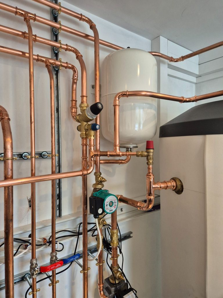
Unlike a combi boiler, a heat pump system needs internal space for:
- an unvented hot water cylinder
- a buffer vessel or volumiser, where needed
- expansion vessels, pumps and controls
- electrical isolators and a controller
- clear access for servicing and replacement
Ideally, the plant space sits close to the external unit and the main hot water outlets. Ask us for typical dimensions for your project at concept stage, so the space is shown on the plans from the start.
Siting the external unit
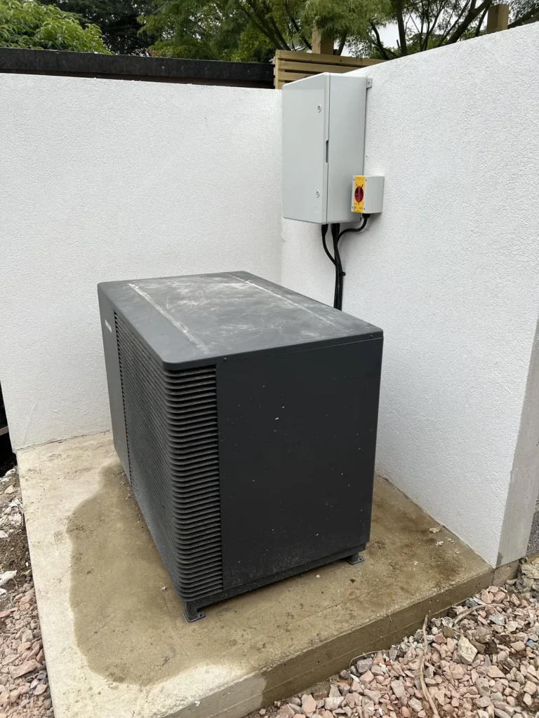
- Airflow: keep clear space in front and behind. Enclosed recesses recirculate cold air.
- Noise: consider the distance to neighbouring windows. Permitted development relies on an MCS noise assessment.
- Visual impact: screen it without blocking airflow, and show it on the elevations early.
- Access: allow safe access for servicing, not ladder-only or boxed-in positions.
- Condensate: defrost water needs a drain or soakaway, away from paths that could ice over.
- Pipe run: keep the route to the plant space short to cut heat loss and cost.
Choosing emitters
| Emitter | Suits flow temperature | Design implications |
|---|---|---|
| Underfloor heating | Around 35°C | Floor build-up and screed depth; slower response |
| Oversized radiators | Around 45°C | More wall space; affects furniture layouts |
| Fan-assisted radiators | Around 45°C | Compact, but need power and make some noise |
| Standard radiators | 55°C and above | Usually undersized; avoid in new designs |
Emitters can be mixed. Underfloor heating downstairs with larger radiators upstairs is a common approach.
Pipework and hot water
- Higher flow rates often mean larger pipes than a boiler system, so coordinate routes with the structure and joists early.
- Insulate all primary pipework fully, and keep external runs short and protected.
- Size the cylinder to the expected occupancy and use. Reheat is slower than a combi boiler, so storage matters.
- A regular pasteurisation cycle controls Legionella.
- Locate the cylinder near the main outlets to reduce dead legs.
One system, not three products
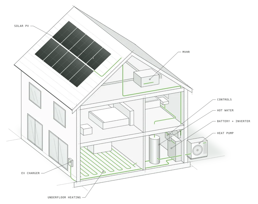
Solar PV, battery storage and a heat pump work best when they’re designed together, with smart controls deciding when to heat, store or export. Coordinated controls let surplus solar heat the hot water and shift heating to cheaper tariff periods. Reserve roof area and orientation for solar PV, and agree a battery location with current fire guidance in mind. Read more about our whole-home approach.
Check the electrical supply early
- Supply capacity: a heat pump, battery, solar PV and EV charger together can exceed an existing supply. Check the main fuse rating.
- Network operator: the distribution network operator (DNO) usually needs to be notified of, or approve, heat pump and generation connections.
- Space and safety: allow room for the inverter, isolators and consumer unit, and site batteries in line with current fire guidance.
The rules that shape the design
| Area | What it means for the design |
|---|---|
| Approved Document L | Energy targets, and a maximum design flow temperature of 55°C or lower for wet heating systems, including heat pumps, in new homes and fully replaced systems |
| Future Homes Standard | Low-carbon heating expected in new homes from 24 March 2027 |
| MCS standards | Heat loss, performance and noise calculations; needed for grants |
| Permitted development | Limits on unit size, siting and noise. Check the current rules for each site |
| Listed buildings and conservation areas | Consent is often required; siting and screening matter most |
Lessons from our projects
- Banbury new build: a large plant room with easy access for maintenance, and a short pipe run to the external unit, made the system simple to install and service.
- Upton-upon-Severn self-build: the hot water cylinders went in the loft to free up living space, which had to be designed for from the start.
- Award-winning timber-frame self-build: underfloor heating pipes laid before the ground floor slab, and a slimmer first-floor build-up agreed with the client.
- 1750s cottage: five correctly sized radiators heat a stone cottage with no central heating before, showing what a proper heat loss calculation makes possible.
Five early decisions that cause problems
- No space allowed for a hot water cylinder.
- External unit squeezed into an enclosed recess or a narrow side passage.
- Emitters sized for a boiler, forcing high flow temperatures.
- Heat pump sized before a proper heat loss calculation.
- Electrical supply and DNO approval checked too late.
A concept-stage checklist
- Heat loss target agreed with the design team
- Plant space and cylinder location shown on the plans
- External unit tested for airflow, noise and visual impact
- Emitter strategy set for low flow temperatures
- Pipe routes coordinated with the structure
- Roof orientation and area reserved for solar PV
- Battery location agreed with fire guidance in mind
- Electrical supply capacity checked
How we support architects
PBT Installations designs and installs complete home energy systems across Gloucestershire and the Cotswolds, bringing heat pumps, solar, battery storage, underfloor heating, ventilation and controls together as one system. We get involved from the start, with early design input at concept stage, and we take responsibility for full system designs, drawings, schematics and room-by-room heat loss calculations, so the heat pump, emitters and plant space are right before your drawings are fixed. Find out more about working with us on your project.
We’re MCS certified (26427), NAPIT registered and TrustMark endorsed, with over 15 years’ experience in extensions, retrofits, new builds and self-builds.
Book a free talk for your practice
We give a free 50-minute talk on designing homes for heat pumps at architectural practices, followed by questions. It covers everything on this page, with examples from real projects. Attendees can log it as CPD on their own records.
Or call us on 01242 323923.